Pollutant Modeling in SWMM
This is where research is being placed as plume generation is investigated. Unless stated otherwise this research is from the SWMM User manual.
Some things to keep in mind about plumes.
- Contaminate Plumes
 1. How are we modeling plumes?
    1. Buildup
    2. Washoff
    3. Initial Contaminate
    4. Dirty rain
    5. Other ways?
 2. How do we shape the plume
    1. Is is a continuous amount over an entire subcatchment?
    2. Can we start at the node level and make that node have the highest contaminate and then radiate out with a lower concentration in a circle?
       1. Can we do this pragmatically or using qgis?
 3. 1 or 2 plumes.
 4. Where do we place the plumes?
    1. It should be random but how do we go about that?
       1. Random number generator?
          1. If we are modeling a plume using subcatchments assign a number to each subcatchment and randomly draw the subcatchment.
          2. For the Node example do the same randomly select a node.
 5. How many plumes
    1. We have both one or 2 plumes to place depending on the scenario.
The Pollutant Editor in SWMM and INP file
According to the SWMM User Manual: A pollutant object is created. It contains the following fields:
- Name - The name assigned to the pollutant.
- Units - The concentration units (mg/L, ug/L, or #/L (counts/L)) in which the pollutant concentration is expressed.
- Rain Concentration - Concentration of the pollutant in rain water (concentration units).
- GW Concentration - Concentration of the pollutant in ground water (concentration units).
- Initial Concentration - Concentration of the pollutant throughout the conveyance system at the start of the simulation.
- I&I Concentration - Concentration of the pollutant in any Infiltration/Inflow (concentration units).
- DWF Concentration - Concentration of the pollutant in any dry weather sanitary flow (concentration units). This value can be overridden for any specific node of the conveyance system by editing the node's Inflows property.
- Decay Coefficient - First-order decay coefficient of the pollutant (1/days).
- Snow Only - YES if pollutant buildup occurs only when there is snow cover, NO otherwise (default is NO).
- Co-Pollutant - Name of another pollutant whose runoff concentration contributes to the runoff concentration of the current pollutant.
- Co-Fraction - Fraction of the co-pollutant's runoff concentration that contributes to the runoff concentration of the current pollutant. An example of a co-pollutant relationship would be where the runoff concentration of a particular heavy metal is some fixed fraction of the runoff concentration of suspended solids. In this case suspended solids would be declared as the co-pollutant for the heavy metal.

The headers that appear to have the most to do with polluant modeling in the inp file are in the image below.
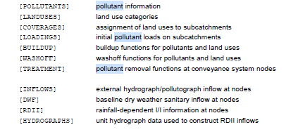
So it looks like pollutants can be added the following ways.
- Loadings
- Buildup
- Washoff
- Rainfall
- Inflow
- DWF
- RDII
[LOADINGS]
Specifies the pollutant buildup that exists on each subcatchment at the start of a simulation.
More than one pair of pollutant - buildup values can be entered per line. If more than one line is needed, then the subcatchment name must still be entered first on the succeeding lines.
If an initial buildup is not specified for a pollutant, then its initial buildup is computed by applying the DRY_DAYS option (specified in the [OPTIONS] section) to the pollutant’s buildup function for each land use in the subcatchment.
[BUILDUP]
Specifies the rate at which pollutants build up over different land uses between rain events.
Buildup is measured in pounds (kilograms) per unit of area (or curb length) for pollutants whose concentration units are either mg/L or ug/L. If the concentration units are counts/L, then the buildup is expressed as counts per unit of area (or curb length).
For the EXT buildup function, C1 is the maximum possible buildup (mass per area or curb length), C2 is a scaling factor, and C3 is the name of a Time Series that contains buildup rates (as mass per area or curb length per day) as a function of time.
[WASHOFF]
Specifies the rate at which pollutants are washed off from different land uses during rain events.
Each washoff function expresses its results in different units. For the Exponential function the runoff variable is expressed in catchment depth per unit of time (inches per hour or millimeters per hour), while for the Rating Curve function it is in whatever flow units were specified in the [OPTIONS] section of the input file (e.g., CFS, CMS, etc.).
The buildup parameter in the Exponential function is the current total buildup over the subcatchment’s land use area in mass units. The units of C1 in the Exponential function are (in/hr) -C2 per hour (or (mm/hr) -C2 per hour). For the Rating Curve function, the units of C1 depend on the flow units employed. For the EMC (event mean concentration) function, C1 is always in concentration units. 328
[TREATMENT]
Specifies the degree of treatment received by pollutants at specific nodes of the drainage system.
Treatment functions can be any well-formed mathematical expression involving:
- inlet pollutant concentrations (use the pollutant name to represent a concentration)
- removal of other pollutants (use R_ pre-pended to the pollutant name to represent removal)
- process variables which include:
- FLOW for flow rate into node (user’s flow units)
- DEPTH for water depth above node invert (ft or m)
- AREA for node surface area (ft2 or m2)
- DT for routing time step (seconds)
- HRT for hydraulic residence time (hours)
Any of the following math functions can be used in a treatment function:
- abs(x) for absolute value of x
- sgn(x) which is +1 for x >= 0 or -1 otherwise
- step(x) which is 0 for x <= 0 and 1 otherwise
- sqrt(x) for the square root of x
- log(x) for logarithm base e of x
- log10(x) for logarithm base 10 of x
- exp(x) for e raised to the x power
- the standard trig functions (sin, cos, tan, and cot)
- the inverse trig functions (asin, acos, atan, and acot)
- the hyperbolic trig functions (sinh, cosh, tanh, and coth) along with the standard operators +, -, *, /, ^ (for exponentiation ) and any level of nested parentheses.
[INFLOWS]
Specifies external hydrographs and pollutographs that enter the drainage system at specific nodes.
External inflows are represented by both a constant and time varying component as follows:
Inflow = (Baseline value)(Pattern factor) + (Scaling factor)(Time series value)
If an external inflow of a pollutant concentration is specified for a node, then there must also be an external inflow of FLOW provided for the same node, unless the node is an Outfall. In that case a pollutant can enter the system during periods when the outfall is submerged and reverse flow occurs.
[DWF]
Specifies dry weather flow and its quality entering the drainage system at specific nodes.
The actual dry weather input will equal the product of the baseline value and any adjustment factors supplied by the specified patterns. (If not supplied, an adjustment factor defaults to 1.0.) The patterns can be any combination of monthly, daily, hourly and weekend hourly patterns, listed in any order. See the [PATTERNS] section for more details. 332
[RDII]
Specifies the parameters that describe rainfall-dependent infiltration/inflow (RDII) entering the drainage system at specific nodes.